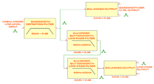
Block diagram of the BWLP-FLTR-MONO board
The Sefirot architecture includes the following boards, all available in this webstore:
-
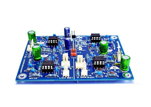
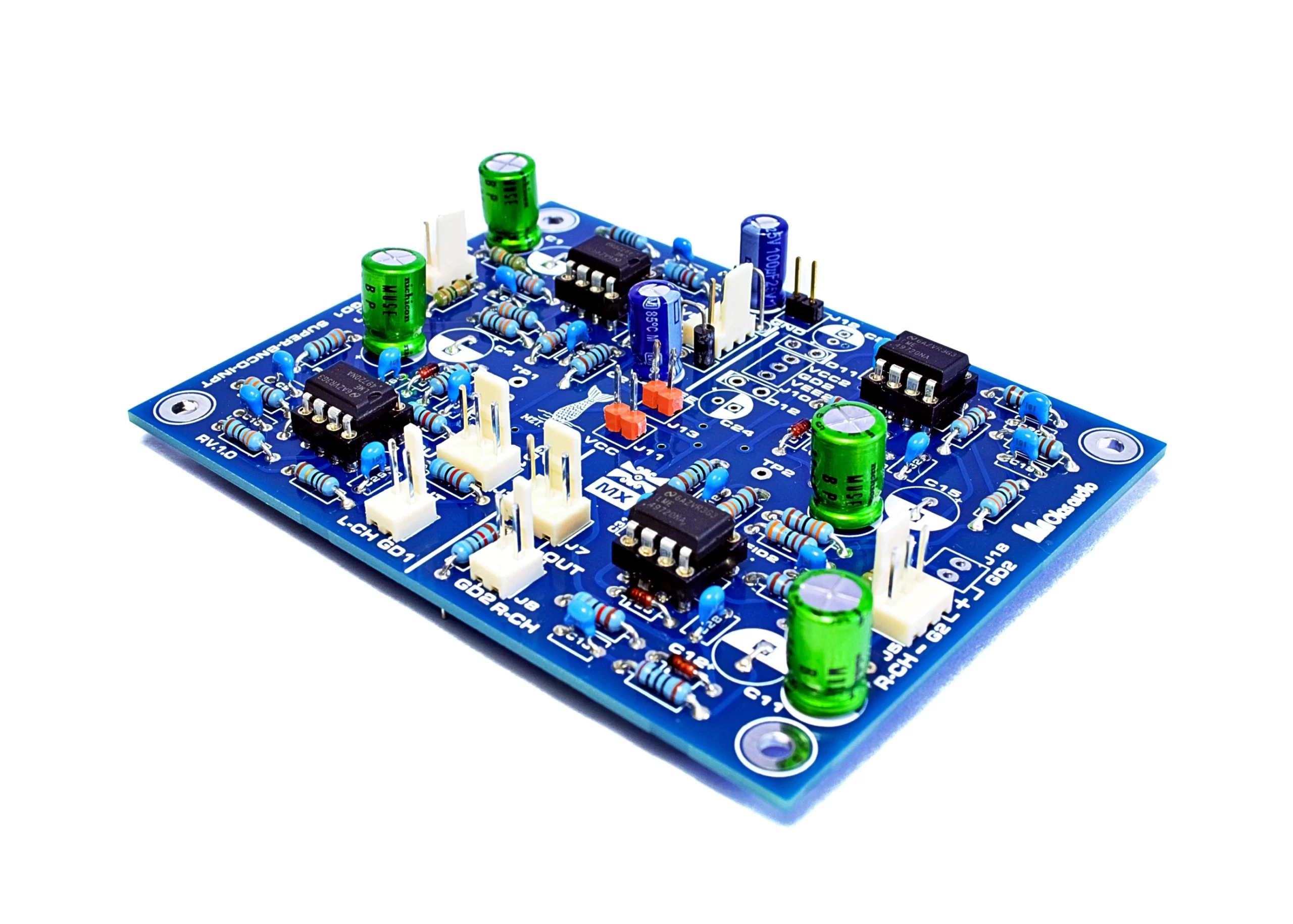
Super Balanced Input (SUPER-BNCD-INPT)
-
Baxandall Volume Control (BAX-VOL-CTRL)
-
Headphone Amplifier Stage (HEADPHONE-OPAMPLFR)
-
Bandwidth Definition & Subbass Low-Pass Filter (BWLP-FLTR-MONO)
-
Summing Amplifier Module ( SUMMING-AMP-L+R)
-
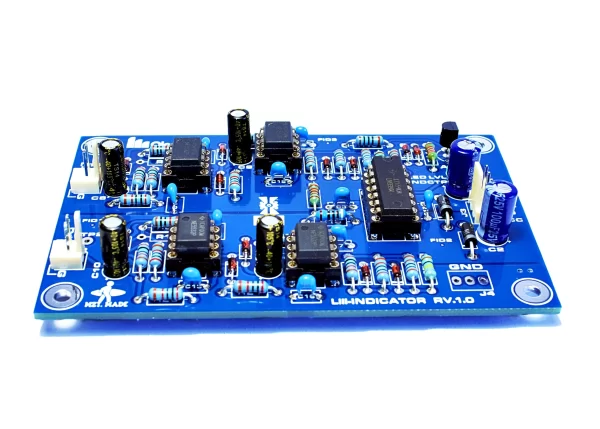
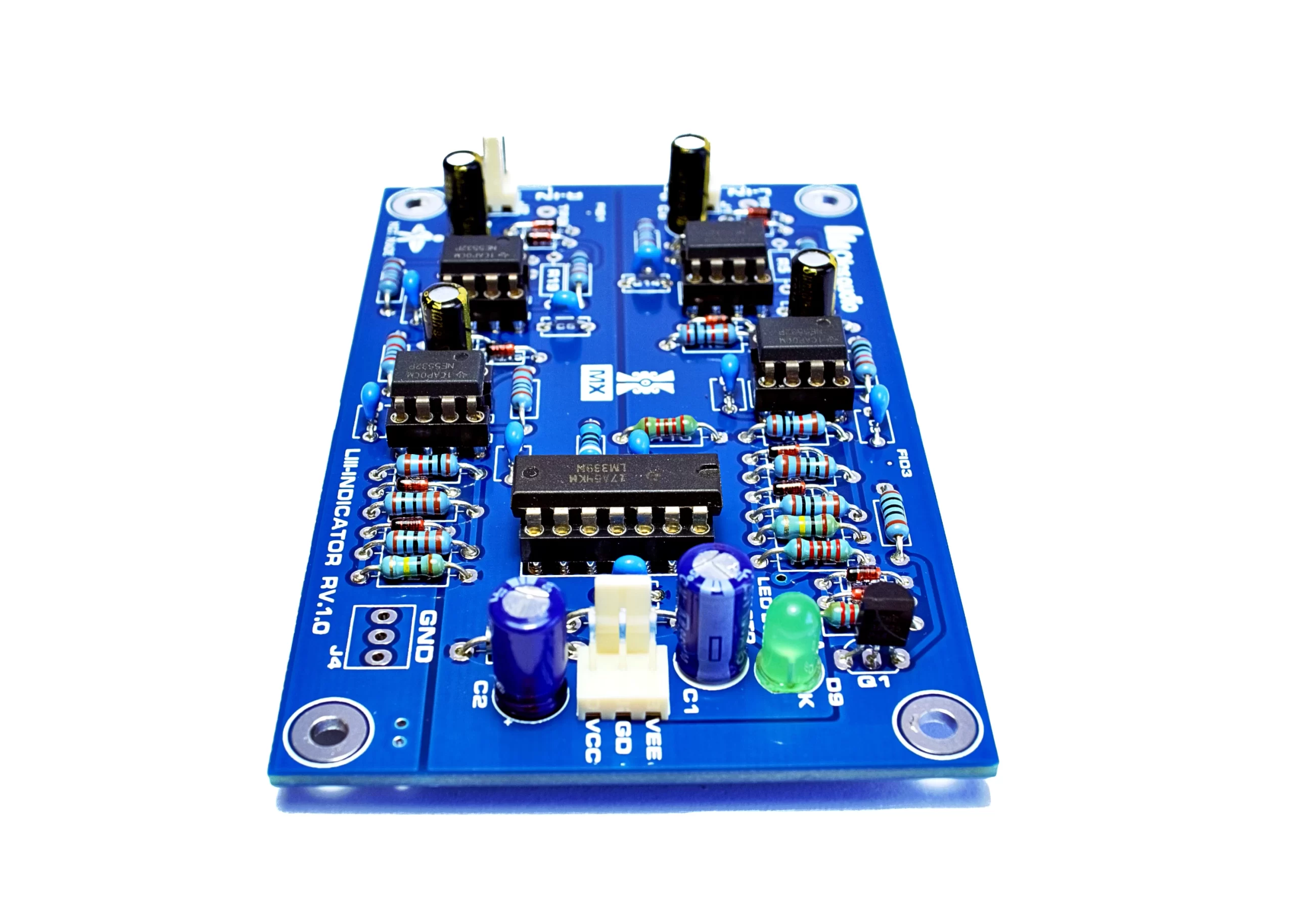
LLLL-INDICATOR Log-Law LED Level System (LLLL-INDICATOR)
-
Power Supply Module (PAMP-PSU)
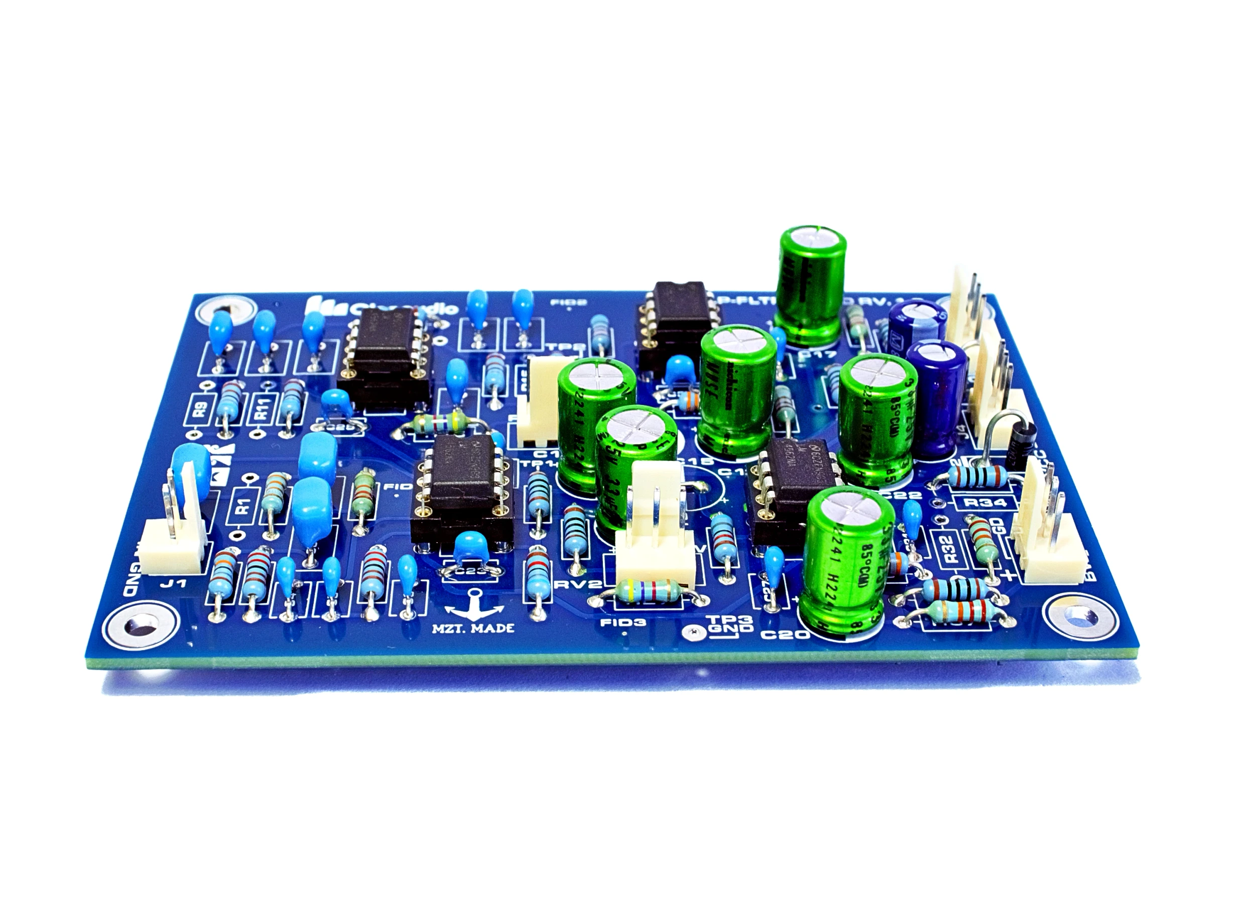
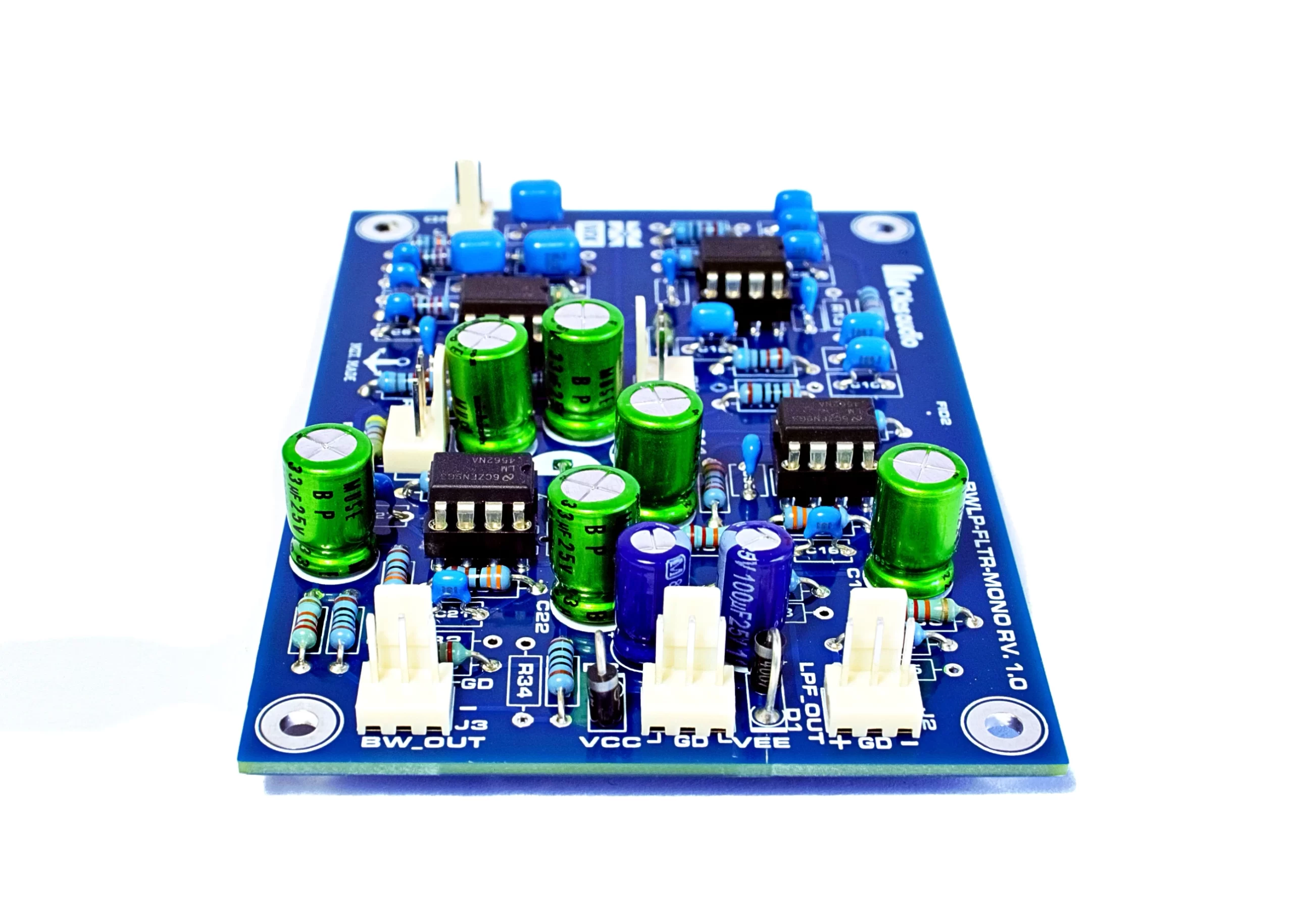
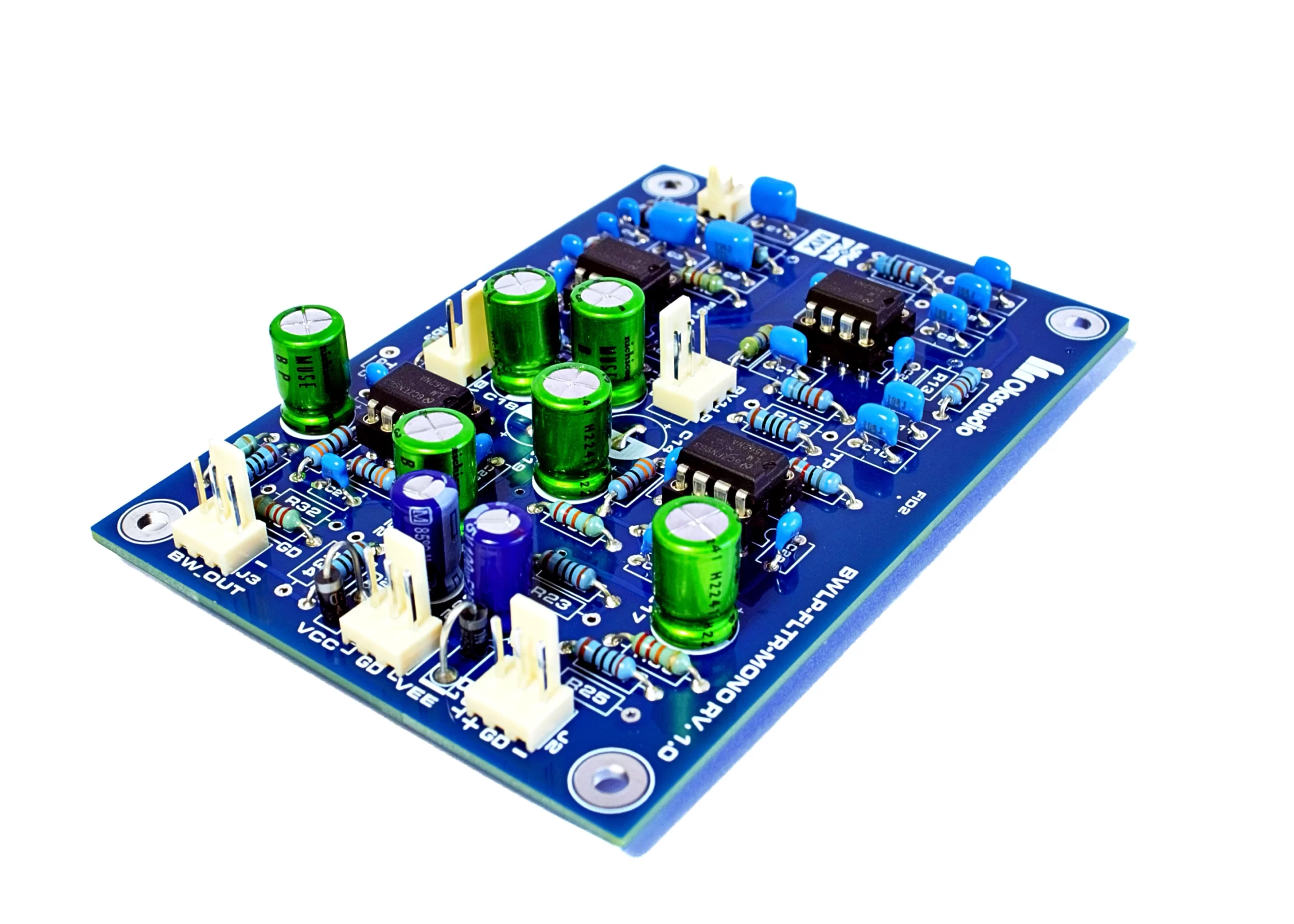
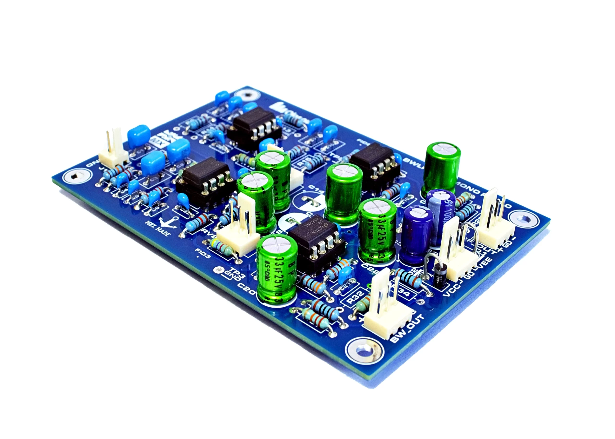
The BWLP-FLTR-MONO board consists of a bandwidth definition filter, a low-pass filter, and a balanced output for each of these stages (see the block diagram for reference). It is primarily designed for audio preamplifiers, bi-amplification systems, and subwoofer amplification.
According to its block diagram, following the bandwidth definition filter, a low-pass filter is implemented, incorporating two 2nd-order Butterworth low-pass filters with programmable frequencies ranging from 80 Hz to 400 Hz. These filters combine to create a 4th-order Linkwitz-Riley low-pass filter, both employing the unity-gain Sallen & Key configuration. At the end of each preceding section along the signal path, there is a balanced output for each segment.
The following are the main features of the BWLP-FLTR-MONO board:
- Mono Input.
- Mono output (for both Low Pass and Bandwidth definition filters).
- Balanced outputs for both type of filters.
- Low Pass Filter THD+N: Vo=1.23 Vrms; 0.00004% at 100 Hz while driving a 600 Ω load.
- Bandwidth Definition Filter THD+N: Vo=1.23 Vrms; 0.00004% at 100 Hz, 0.00003% at 1kHz and 0.00009% at 10 kHz while driving a 600 Ω load.
- Cutoff frequency for 4th order LP filter: (-6 dB): 165Hz
- Cutoff frequency for Bandwidth Definition filter: 50 kHz
- Frequency response for LP filter: -0.6 dB at 20 Hz and -39 dB at 500 Hz.
- Frequency response for Bandwidth Definition filter: -0.6 dB at 20 Hz and -0.48 dB at 20 kHz.
- High-quality double-sided plated-through-hole (Lead-free HASL) PCB with solder mask on both sides and full screen print.
- Gain loss in the mid band of -0.35 dB
- Input impedance: > 28 kΩ
- Current consumption: 85 mA Max.
- PCB size: length=100mm, width=70 mm. It incorporates four M3 fixing holes.
A couple of interconnection diagrams to build a preamplifier using different boards designed by Olas Audio are displayed below.
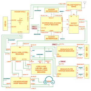
Interconnection between different Olas Audio boards to build a preamplifier with two separate Low pass/Bandwidth Definition filters
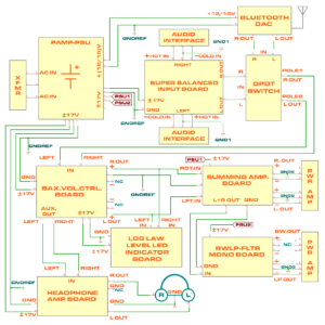
Interconnection between different Olas Audio boards to build a preamplifier with one Summing Amplifier and a Low pass/Bandwidth Definition filter
The published price is for the PCB only. A bill of materials and assembly instructions will be provided upon purchase.