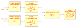
Block diagram of the LLLL-INDICATOR board
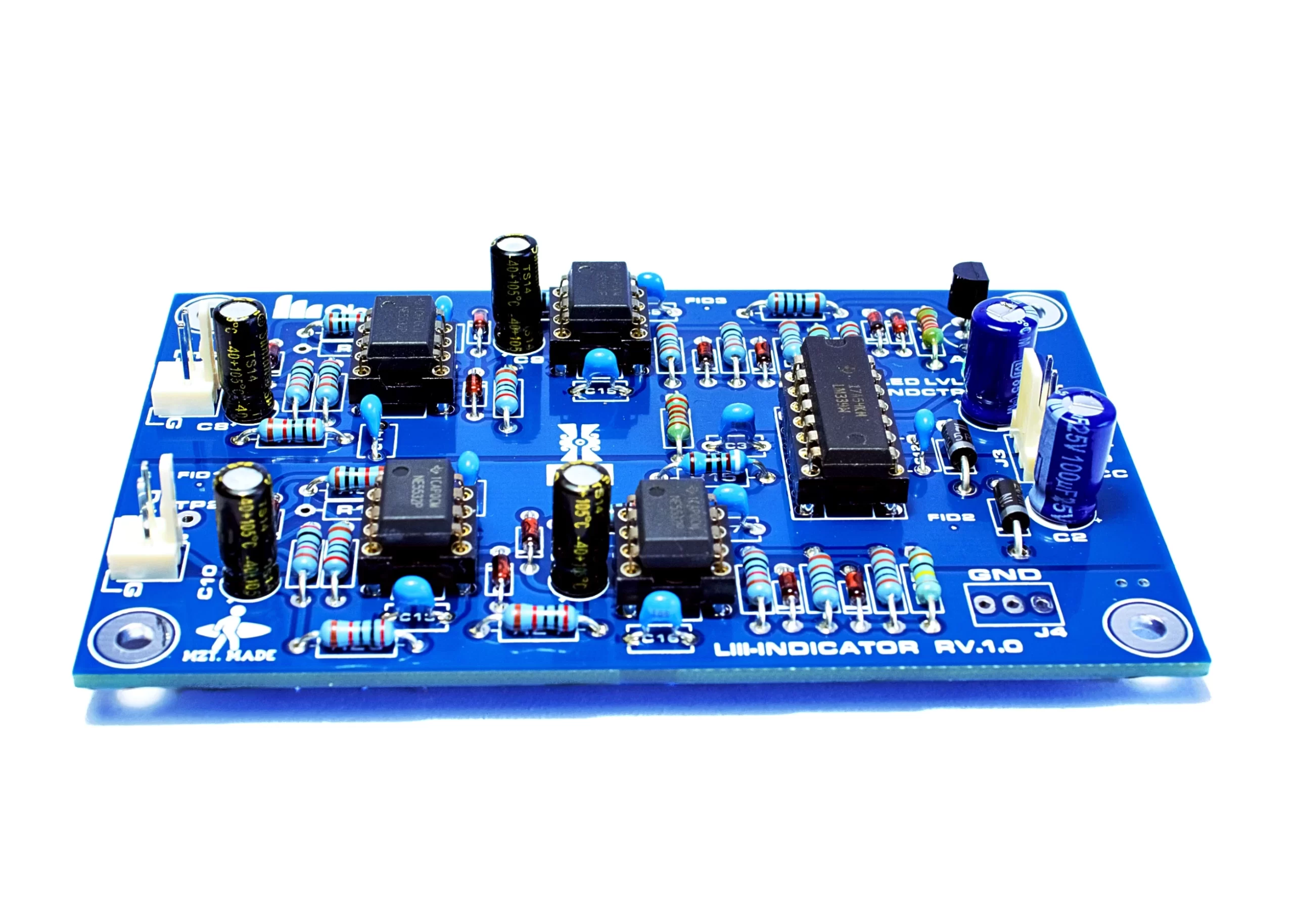
The LLLL-INDICATOR board was specifically designed as a level indicator for audio preamplifiers, headphone amplifiers and power amplifiers. It accommodates a precision rectifier followed by a logarithmic converter; both of these building blocks operation is based on several Op Amps. After the logarithmic converter stage, a comparator is employed to detect the levels of the incoming audio signal, activating an LED indicator accordingly.
The signal flow described earlier is applicable to each channel (Left and Right), and the comprehensive schematic is illustrated in its block diagram. The design of this board draws inspiration from Douglas Self’s Log Law Level LED indicator circuit.
The following are the main features of the LLLL-INDICATOR board:
- Stereo sensing capability
- It provides more information than a peak meter using just one LED
- This board is useful for adjusting a preamplifier so that the correct level is achieved when the LED is illuminated approximately 50% of the time.
- Input impedance > 10 kΩ
- Level range is approximately 10 dB (from LED always-off to always-on).
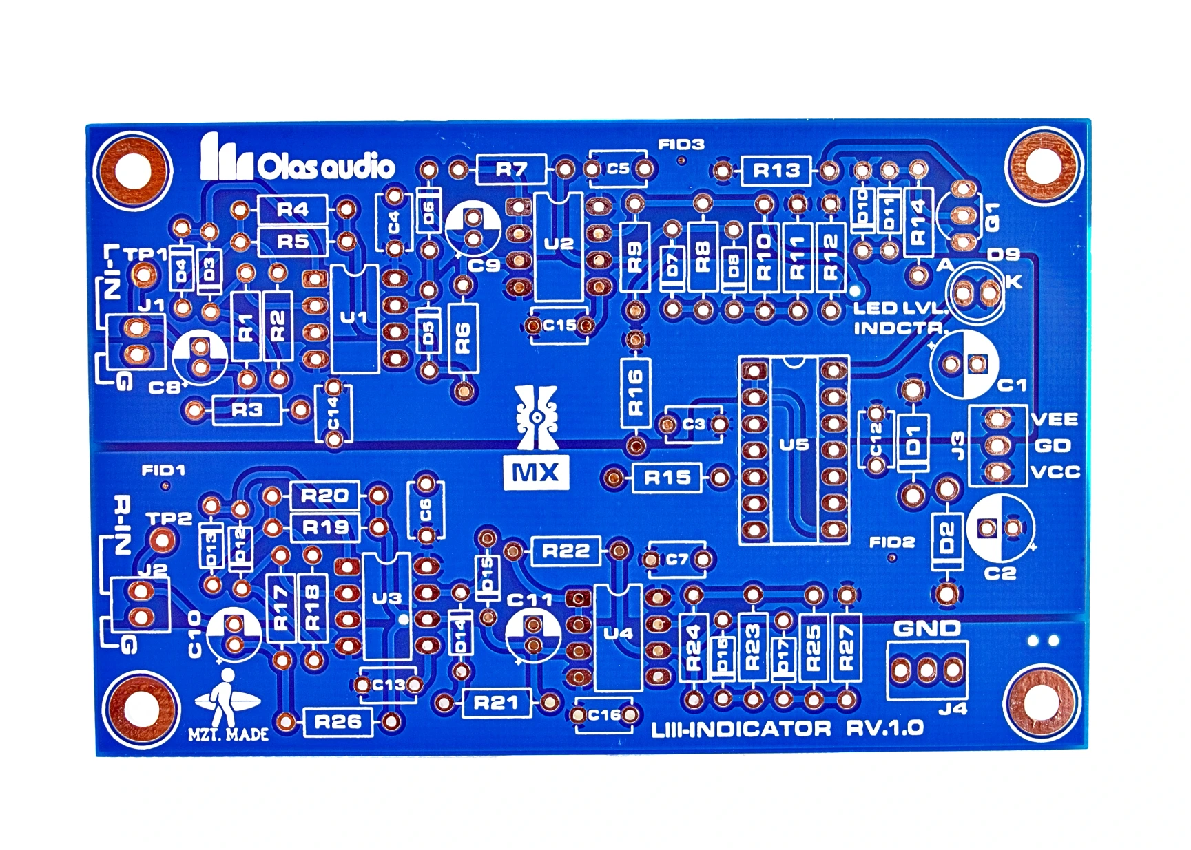
- High-quality double-sided plated-through-hole PCB (Lead-free HASL) with solder mask on both sides and full screen print.
- Current consumption: 80 mA Max.
- PCB size: length=96mm, width=61 mm. It incorporates four M3 fixing holes.
A couple of interconnection diagrams to build a preamplifier using different boards designed by Olas Audio are displayed below.
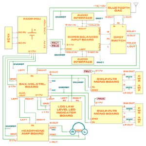
Interconnection between different Olas Audio boards to build a preamplifier with two separate Low pass/Bandwidth Definition filters
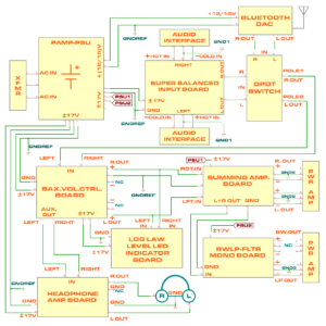
Interconnection between different Olas Audio boards to build a preamplifier with one Summing Amplifier and a Low pass/Bandwidth Definition filter
The published price is for the PCB only. A bill of materials and assembly instructions will be provided upon purchase.