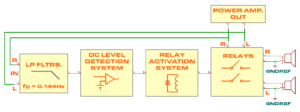
Block diagram of the SP-DR1200 board
Connecting a loudspeaker to a capacitor-coupled (CD) amplifier without proper protection poses a risk not only to the integrity of the speaker but also to user safety, as the voice coil could overheat and potentially cause a fire.
The SP-DR1200 loudspeaker protection system provides an activation delay of 3.9 seconds or more (this time can be easily adjusted) and disconnects the loudspeakers used with the CSS-4700 amplifier in less than 13 milliseconds (excluding the relay stabilization time).
The system operates using a first-order low-pass filter with an approximate cutoff frequency of 0.144 Hz and a comparator with a detection threshold of no more than ±2V. The design is implemented with discrete components, allowing the board to function across a wide range of voltages, from ±18V to ±35V.
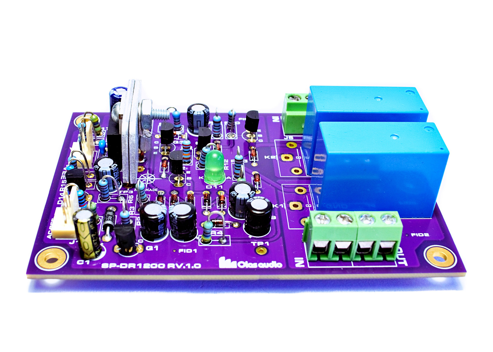
The SP-DR1200 board provides two channels for constructing a stereophonic system. The PCB also includes footprints for two different relay types.
The following are the main operating characteristics of the SP-DR1200 board:
- Two channel protection system based on relay activation.
- Ultra-low noise and low harmonic distortion for highest quality sound.
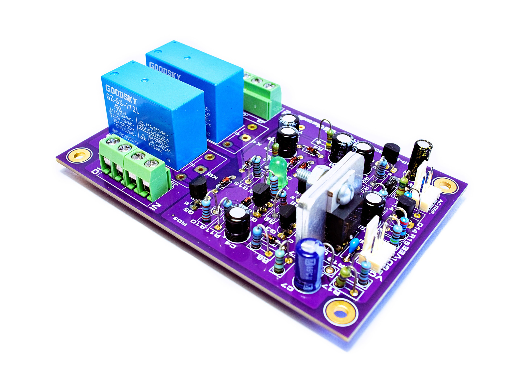
- Can be configure to operate at 12V or 24V for different relay activation conditions (normally open type).
- Slow-on, fast-off action so no transients are passed to the loudspeakers at power-up or power-down.
- Fast positive or negative DC offset voltage detection and AC line faults.
- Two separate filters for each channel, with a cutoff frequency of 0.144 Hz.
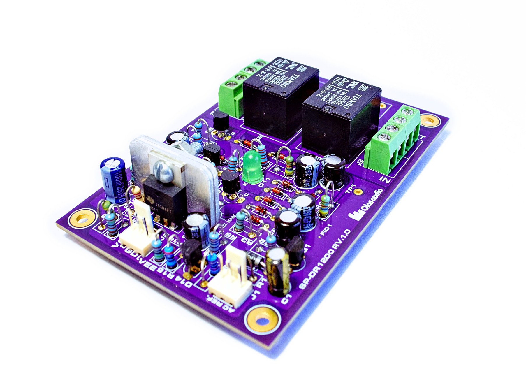
- THD+N: 000054% @ 1 kHz @ 1W and 0.00011% @ 40 W into 8Ω load. Tianbo HJR-3FF-S-Z relay driven at 12 Volts
- THD+N: 001% @ 10 kHz @ 1W and 0.0015% @ 40 W into 8Ω load. Tianbo HJR-3FF-S-Z relay driven at 12 Volts
- Turn on delay to avoid thumps and noises at power up.
- High-quality double-sided plated-through-hole PCB (ENIG Gold Fingers: 1U”) with solder mask on both sides and full screen print.
- PCB size: length=100mm, width=66 mm. It incorporates four M3 fixing holes.
- Power-up activation of 3 to 4 seconds to avoid thumps and other noises
- Disconnection time of 13 milliseconds when the power supply is switched off
- Approximate disconnection time of 28 milliseconds in the presence of an offset voltage in the output signal
- Relay on/off indicator LED
- Detection is done with negative and positive levels
- Use of terminal block connectors to facilitate interconnection with the CSS-4700 composite amplifier board output terminals
The following diagrams illustrate the configurations in which you can integrate this board with other Olas Audio products.
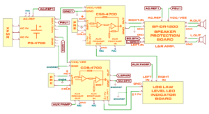
Interconnection between different Olas Audio boards to build a stereo audio power amplifier. This version includes one PS-4700 Power Supply Unit, two channels of amplification (left and right), a Log Law Level LED indicator board and a Speaker Protection board.
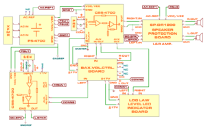
Interconnection between different Olas Audio boards to build a stereo audio power amplifier. This version includes one PS-4700 Power Supply Unit, two channels of amplification (left and right), a Baxandall Volume Control board, a Log Law Level LED indicator board and a Speaker Protection board.
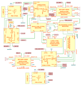
Interconnection between different Olas Audio boards to build an audio power amplifier with a bi-amplification scheme. This version includes two PS-4700 Power Supply Unit boards, three channels of amplification (left, right, and one for subbass signals), a Baxandall Volume Control board, a Log Law Level LED indicator board, a Summing Amplifier board, a Bandwidth Definition/Low Pass Filter board and a couple of Speaker Protection boards.
The published price is for the PCB only. A bill of materials and assembly instructions will be provided upon purchase.